





How skeletal trailer dimensions affect container loading flexibility
Container transport flexibility is determined less by the nominal “20 ft” or “40 ft” label than by how a skeletal trailer positions the container’s corner castings over its kingpin, axles, twistlocks, and rear extremity. A chassis can be structurally sound yet create avoidable delivery constraints if its lock positions, axle group location, turning envelope, or overall length do not match the container mix and route conditions of a project.
For project delivery, the practical question is not simply whether a trailer can carry a container. It is whether it can carry the required container type at a legal axle load, enter the site, turn within the available space, clear ramps and uneven ground, and remain useful when the shipping plan shifts between 20 ft, 40 ft, high-cube, or specialized units. Skeletal trailer dimensions therefore affect schedule resilience as much as they affect payload.
Container length is only the starting point
Standard dry containers are commonly described by nominal lengths of 20 ft and 40 ft. Their external dimensions are standardized around corner-casting interfaces: a typical 20 ft ISO container is approximately 6,058 mm long, while a 40 ft unit is approximately 12,192 mm long. Standard external width is generally 2,438 mm. Heights vary, with high-cube containers being taller than standard-height units.
These measurements do not translate directly into a chassis design length. The trailer must provide twistlock stations at the correct longitudinal spacing, while also accommodating clearance at the front and rear, the kingpin-to-container relationship, mudguards, suspension movement, lights, bumper geometry, and jurisdiction-specific rear-underrun requirements. A trailer described as “40 ft” may therefore have an overall length substantially different from the container it carries.
For a transport plan involving only one container format on predictable paved routes, a fixed-length chassis may be sufficient. Flexibility becomes more important when container availability is uncertain, when shipping lines substitute equipment, or when a project combines imported equipment in containers with regional repositioning work. In those conditions, skeletal trailer dimensions should be evaluated as a compatibility system rather than as a single length figure.
Twistlock layout determines real loading flexibility
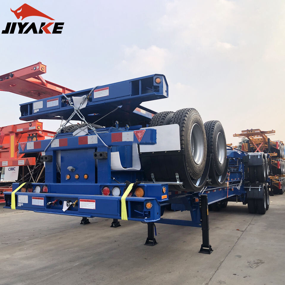
The critical dimensional feature is the twistlock pattern. Twistlocks secure the lower corner castings and establish the load path from the container into the trailer frame. A multi-position skeletal chassis can support different container lengths only if its locking points correspond precisely to the relevant container corner locations.
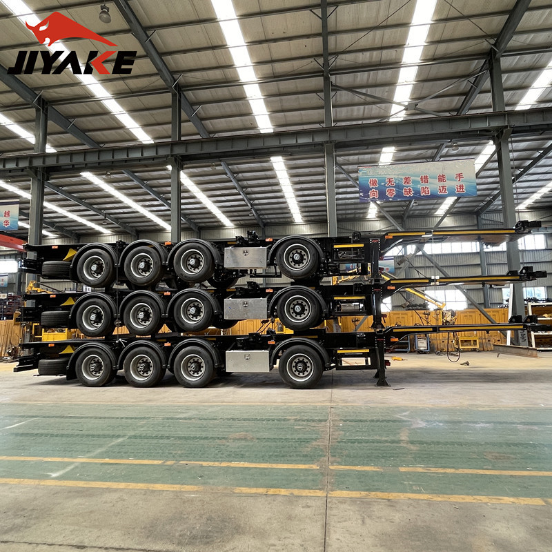
A common configuration supports one 40 ft container or one 20 ft container in a specified position. More flexible arrangements may be designed for 20 ft and 40 ft units, two 20 ft containers, or selected 45 ft container formats. However, the phrase “multi-container compatible” should not be accepted without checking the actual lock map. The following distinctions matter:
- Single 20 ft position: The container may sit centrally or toward the rear, depending on axle-load requirements and local rules. These positions are not interchangeable.
- Two 20 ft positions: Carrying two 20 ft containers requires independent lock stations and adequate structural design for the load distribution. A chassis that carries one 40 ft container is not automatically suitable for two 20 ft units.
- 40 ft and 45 ft capability: A 45 ft container introduces additional length and rear projection considerations. Compatibility depends on chassis extension design, lock placement, and the applicable road regime.
- Specialized containers: Reefer units, tank containers, open-top units, and certain project cargo containers can differ in tare weight, center of gravity, or operating clearance even when their corner-casting footprint is nominally standard.
Movable twistlocks and extendable rear sections increase operating options, but they also introduce inspection and operating requirements. Operators need clear confirmation that sliding members are fully engaged, pins are locked, and unused locking devices do not interfere with container placement. A flexible configuration only improves scheduling if it can be changed quickly and reliably without creating a new loading-control risk.
Axle position governs both legality and site performance
Container loading flexibility is constrained by axle loading. A container may fit physically on the trailer but still be unsuitable for the intended route if its weight distribution overloads the tractor drive axle, trailer axle group, or steering axle. This is particularly important with dense cargoes, where a 20 ft container can weigh more than a longer 40 ft container.
The longitudinal distance between the kingpin, the container’s front corner castings, and the trailer axle group determines how much load is transferred to the tractor and to the trailer. A rearward container position can reduce one axle group’s load while increasing another’s. A forward position can have the opposite effect. The acceptable arrangement depends on the gross combination weight, tractor specification, national or regional axle limits, and the container’s actual center of gravity.
This is why a project team should request axle-load calculations for representative loading cases rather than relying on a chassis payload headline. At minimum, calculations should cover the heaviest anticipated 20 ft container, a normally loaded 40 ft container, and any non-standard container type expected in the shipment plan. If two 20 ft containers may be moved together, that configuration needs its own assessment because the gap between units and the distribution of cargo within each box materially affect axle loads.
Axle spacing also affects maneuverability. A longer axle group arrangement may offer stability benefits but can increase swept path during turns. On constrained construction access roads, temporary logistics yards, and ports with tight stacking lanes, the practical limitation may be turning geometry rather than gross weight. The trailer’s wheelbase, rear overhang, and steering behavior of the tractor should therefore be reviewed against the tightest site movement, not only against highway travel.
Overall length affects route approval and terminal access
Overall skeletal trailer dimensions affect route planning because road authorities regulate vehicle length, axle loads, turning behavior, rear projection, and, in some markets, the operating conditions for extended combinations. The applicable limits vary by country and can differ between public roads, port areas, industrial zones, and controlled project sites. A chassis intended for cross-border work should not be assessed against the regulations of only one loading country.
Extension frames deserve particular attention. An extendable skeletal trailer may allow a fleet to cover 40 ft and longer containers without maintaining separate fixed-length units. Yet its extended configuration can change the vehicle’s turning circle, rear swing, bridge loading characteristics, and access through gates or weighbridge lanes. The extension mechanism also adds a planning question: whether the required configuration can be set safely before dispatch and whether the route permits travel in that extended state.
Height is often overlooked because the container itself sets most of the loaded profile. In practice, deck height and tire diameter affect loaded height, ramp clearance, and the stability margin on sloped or uneven ground. A high-cube container on a high-frame skeletal trailer can create clearance issues beneath gantry structures, building canopies, utility lines, or site access barriers even where the road route is otherwise acceptable.
Site geometry can negate nominal trailer compatibility
A container chassis selected only for road movement can become inefficient at the destination. Construction projects often rely on temporary unloading zones with unfinished surfaces, narrow gates, unpaved turning areas, and limited room for reversing. Long rear overhang increases the risk of striking site barriers or grounding on abrupt grade changes. Low ground clearance can be problematic where site roads have ruts, loose aggregate, or drainage crossings.
Ground conditions also affect the sequence of work. A skeletal trailer is designed to transport a container, not to provide a stable unloading platform on poor terrain. Where containers must be lifted by crane, reach stacker, sideloader, or forklift-compatible handling equipment, the project plan needs enough level, compacted area for both the trailer and the lifting operation. Trailer dimensions influence the space required to position the unit, but they do not eliminate the need to verify handling equipment capacity and reach.
The same principle applies when containers are used as temporary storage near a work face. A chassis may deliver the unit successfully, while the intended placement area remains inaccessible due to turning radius, crane setup space, or insufficient approach length. Transport dimensions should be assessed together with the container’s final placement geometry.
Do not confuse frame capacity with container compatibility
Frame strength, suspension rating, tires, brakes, and landing gear establish the chassis’s operating capacity, but they do not by themselves confirm container flexibility. A trailer can have robust axles and still lack the lock positions needed for the required container combination. Conversely, a chassis with many lock positions may not be suitable for the heaviest load case if axle distribution has not been validated.
This distinction is useful when reviewing other trailer types used within the same project logistics chain. For example, a Cement Bulker Trailer may use a three-axle arrangement and a substantial tank structure to move dry bulk material to a batching plant, but its 11,900 × 2,500 × 3,900 mm envelope and bulk-powder discharge system address an entirely different transport task. Similar axle counts or nominal dimensions do not make a bulk tanker and a container skeletal trailer operational substitutes.
Specification checks that prevent late changes
Before assigning a skeletal trailer to a project, the transport specification should state more than “20 ft/40 ft compatible.” It should identify the exact container sizes, whether two 20 ft units may be carried, whether high-cube or 45 ft units are included, and whether tank containers or overweight cargo are possible. The supplier’s dimensional drawing should show the kingpin location, axle-group centerline, twistlock centers, overall length in every extension state, rear overhang, loaded deck height, and tire specification.
It is also necessary to align the trailer drawing with the tractor unit. Fifth-wheel height affects running level and clearance; tractor wheelbase affects turning performance; and the tractor’s permitted axle loads affect whether a given container position is usable. A skeletal chassis should be specified as part of a tractor-trailer combination, not as an isolated frame.
The most useful outcome is a small set of approved loading configurations tied to actual project cargo and routes: for example, a defined lock position for a heavy 20 ft machinery container, a separate configuration for a standard 40 ft materials container, and a route-specific decision for any extended unit. That approach turns skeletal trailer dimensions from a procurement detail into an operational control, reducing the chance that a container arrives at the gate, port, or site only to require a different chassis, a different tractor, or a revised delivery plan.
Leave A Reply

First class quality service and professional after-sales team.
Get in Touch
*We respect your confidentiality and all information are protected.