





How to choose twist locks for a skeleton semi-trailer
Choose twist locks by starting with the containers and loading positions the skeleton semi-trailer must accommodate. The locks must engage the correct corner castings, carry the forces assigned to them, and remain securely locked throughout the journey. A trailer’s payload rating alone cannot establish that the locks or their mounting points are suitable.
Start with the container layout
Identify every intended loading arrangement before selecting the locks: one 20-foot container, one 40-foot container, a 45-foot container, or multiple containers where the chassis is designed for them. Each arrangement places the corner castings at different positions. A lock at the extreme end of a long chassis does not secure a shorter container unless a corresponding intermediate position is provided.
For each arrangement, compare a dimensioned chassis drawing with the container’s corner-casting locations. Confirm the longitudinal and transverse spacing, the height of each seating surface, and whether adjacent locks or chassis members obstruct the container during loading. The lock head must enter the casting and turn fully; the container must also sit properly on its intended supports.
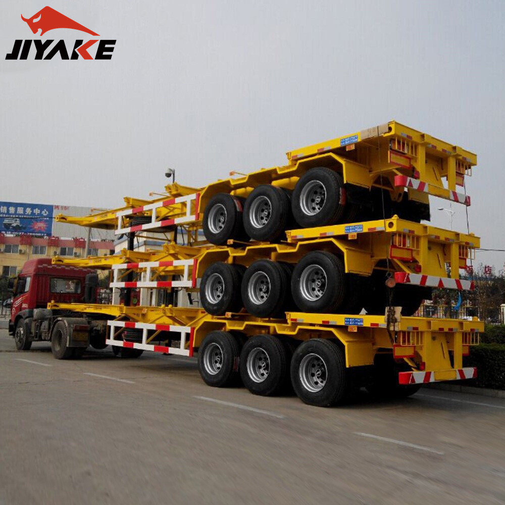
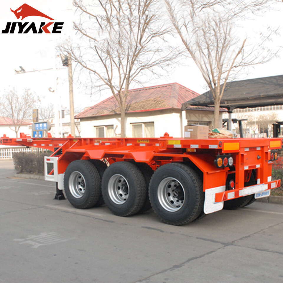
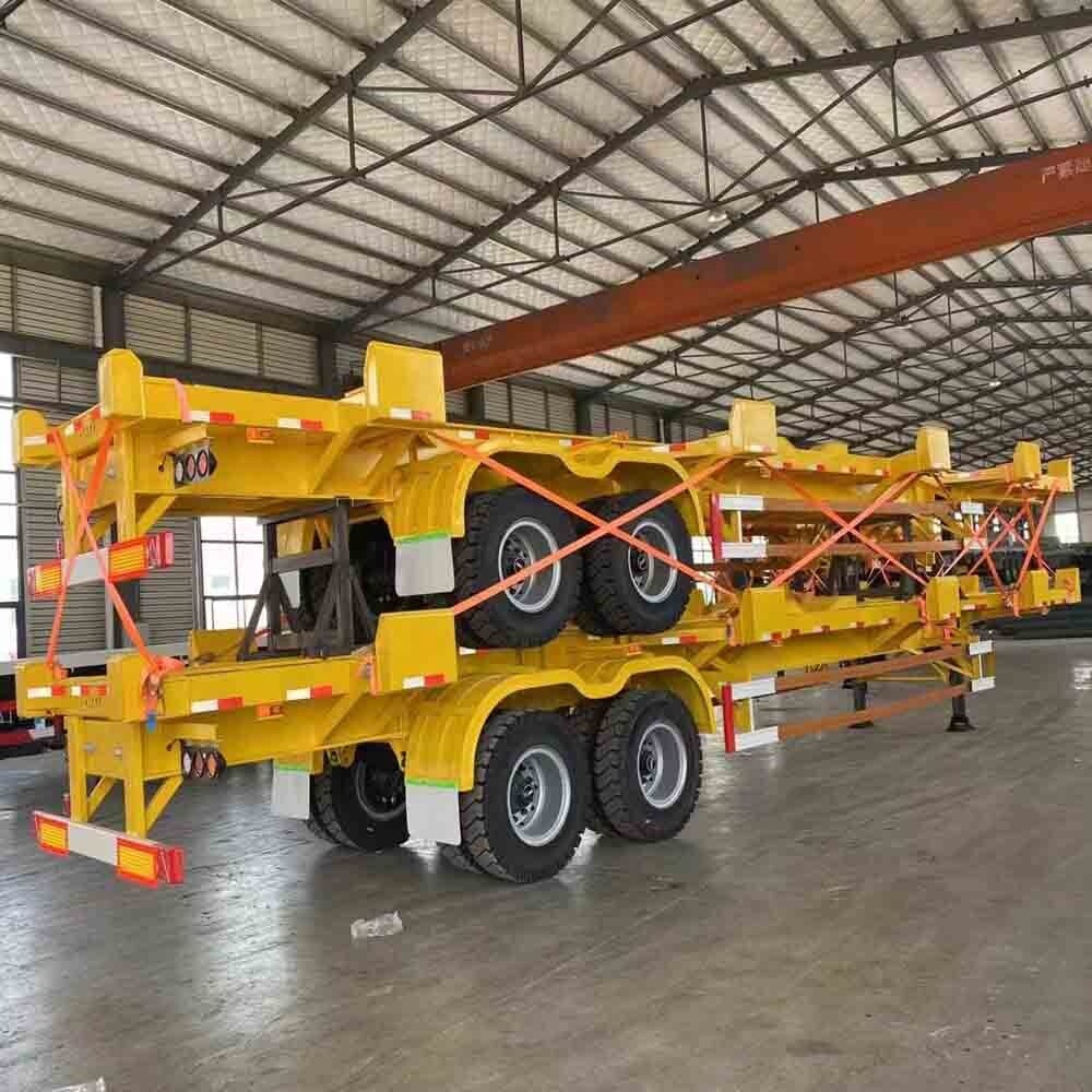
The listed configuration for the 2 Axle Skeleton Semi Trailer includes four twist locks for one 40-foot container, with 20-foot, 40-foot and 45-foot container applications described in the product information. That four-lock configuration should not be assumed to secure every listed container size: request the position drawing and lock count for each intended loading arrangement. Confirm the permitted axle configuration and loading distribution at the same time.
Read the lock rating in context
A twist lock resists forces in several directions. Vertical separation, longitudinal movement during braking and acceleration, and lateral movement during cornering do not necessarily have the same permissible values. Ask for the rated capacity in the relevant directions, the basis of those ratings, and the installation conditions under which they apply.
Do not divide container gross mass by the number of locks and treat the result as a complete selection calculation. Dynamic forces, uneven load distribution, chassis flexibility and the position of the container’s center of gravity affect the forces at individual attachments. The container floor supports also carry vertical load; the way the lock and support share forces depends on the design.
Assess the entire load path from the corner casting through the lock body and its attachment into the chassis. A high-rated lock installed in an inadequately reinforced crossmember does not make the assembly adequate. Conversely, a strong chassis cannot compensate for a lock whose rating or engagement geometry is unsuitable. Obtain documentation for the assembled mounting arrangement, including any applicable transport and load-securing requirements for the routes involved.
Choose a mechanism that fits the loading operation
Fixed, retractable and removable lock arrangements solve different access problems. Fixed locks keep the attachment points readily available, but their projecting heads must suit the loading method and container positions. Retractable or fold-down designs can clear unused positions when different container lengths share a chassis. Removable units offer flexibility, provided there is a defined way to retain, identify and inspect them.
Compare the operating mechanism as well as the nominal lock type. A manually turned handle needs enough clearance beside the rail and any nearby brackets for a full movement. The locked position should be apparent, and a retaining feature should prevent unintended rotation. A handle that reaches its stop while the head is only partly engaged is a reason to reject or correct the installation.
Before specifying a recessed mechanism, examine drainage and access for cleaning. A pocket that collects road grit, water or hardened cargo residue can make the lock difficult to operate. In frequent container changes, accessible lubrication points and replaceable wear parts are practical selection criteria.
Mounting details determine whether a lock works as rated
For welded locks, review the specified attachment surfaces, weld details and reinforcement with the chassis design. Welding directly to a beam flange or cutting away material to create clearance can affect the structural member; alterations require an approved engineering assessment. The material of the lock housing and the chassis, welding procedure and heat input also matter to the integrity of the joint.
For bolted assemblies, compare the hole pattern, bolt specification, clamping arrangement and access for tightening. Slotted holes may assist positioning where the design permits them, but they are not a substitute for correct engagement or a secure attachment. Verify that fasteners cannot interfere with the container seating surface or the mechanism’s movement.
Lock height deserves particular attention. If one support stands higher than the others, the container can rock or impose uneven reactions on the frame. If a lock sits too low, the head may not engage the casting as intended. Measurements should be taken on the finished chassis, including coating or other details that affect contact, rather than relying solely on the component drawing.
Confirm fit before accepting the configuration
A drawing comparison is the first filter; a physical trial with the intended container type reveals issues that dimensions alone can miss. Lower the container onto the designated supports and confirm that each head enters its casting without forcing the container sideways. Rotate every lock through its full travel, engage the retainer and verify that the locked indication agrees with the actual head position.
Repeat the trial at every specified container position. A 40-foot arrangement that works correctly does not demonstrate that intermediate locks align with a 20-foot container. Where two short containers are intended, verify that the chassis has the required attachment points and supports for both, and that the combined mass and axle loads remain within the approved limits.
Record the lock identification, rated directions, mounting details and approved loading layouts with the trailer documentation. This makes replacement easier: a visually similar lock can have a different head geometry, height, operating direction or load rating.
Inspect wear at the connection, not only at the handle
During service, look for a head that turns stiffly, fails to reach its locked position or has excessive movement in the housing. Examine the contact surfaces, retaining device, mounting bolts or welds, and the surrounding chassis for damage or deformation. A loose handle can indicate wear in the mechanism; movement of the entire housing points toward its attachment or supporting structure.
Container corner castings also affect engagement. Distortion, heavy contamination or damaged openings can prevent a sound lock from seating correctly. Clean and inspect the contact area before attributing every fit problem to the trailer.
Remove a damaged or uncertain attachment from service until it has been assessed and repaired using an approved method. Replacement parts should match the documented assembly, and the completed mechanism should be tested through its full locking cycle before the trailer returns to container transport.
Leave A Reply

First class quality service and professional after-sales team.
Get in Touch
*We respect your confidentiality and all information are protected.